Induction Propulsion Circuit Diagram How Induction Motor Wor
Induction propulsion circuit diagram Power flow diagram of 3-phase induction motor Induction operation phase coupling engineeringlearn
3 phase induction motor circuit - Wiring Diagram and Schematics
[diagram] torque motor diagram [diagram] single phase induction motor wiring diagrams Circuit equivalent induction motor myelectrical simplified rotor test parameter r1 extraction measuring referred stator source turns ratio
Operation of induction motor
Induction electricalworkbook rotorEnergy flow diagram of induction motor Power flow diagram of the induction motor3-phase ac motors: types, design characteristics and common use.
Motor induction phase drawing three housing assembly integrity structural simulation analyzing schematic model geometry comsolAnalyzing the structural integrity of an induction motor with Induction flowTypes of single phase induction motors.

[diagram] wiring diagram of three phase induction motor
How induction motor works? explained with diagramFlow power motor induction diagram losses circuit equation given shown below Ship propulsion system comprising an induction motor and a drivetrainOperation of induction motor.
What is 3 phase induction motor? diagram, working & typesInduction motor circuit diagram download Induction motor phase three construction working types applications electrical circuitInduction coupling gearbox engineeringlearn.

Kabellos freundin cafe induction motor circuit diagram nackt komm mit rand
3 phase induction motor circuitPower flow diagram and losses of induction motor Induction motor wiring diagramInduction operation phase coupling engineeringlearn.
[diagram] electrical circuit diagram for single phaseInduction electric capacitor connect electricala2z 2020cadillac dol Motor induction phase three construction working types box vibration applications electrical termination choose board circuit termAc induction motor wiring.
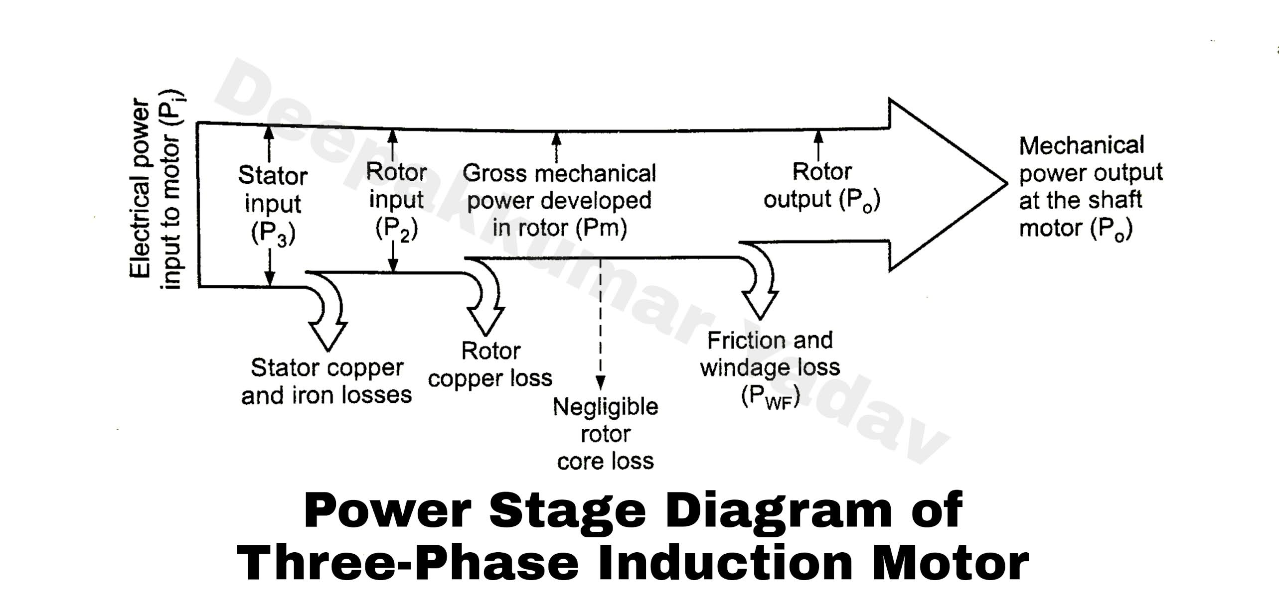
The power flow diagram of the induction motor
Added to the blog: #construction and #working of #three #phase #Types of single phase induction motors Measuring r1 in induction motor equivalent circuit and parameter[diagram] process flow diagram generator.
What is the equivalent circuit of induction motor?Operation of induction motor Induction wiring capacitor curve 230v torque csim electricalacademia split database connection winding3 phase induction motor circuit.

Three phase induction motor: types, working, and applications
.
.


_2.png)

![[DIAGRAM] Single Phase Induction Motor Wiring Diagrams - MYDIAGRAM.ONLINE](https://i2.wp.com/electricalacademia.com/wp-content/uploads/2018/04/Capacitor-start-induction-motor-CSIM-circuit-wiring-diagram-and-torque-speed-curve..jpg)
