Skip to content

Indicator Diagram For Two Stroke Engine Stroke Engine Diagra

Indicator Diagram For 5 Stroke Engine | Diagram, Engineering, Diesel

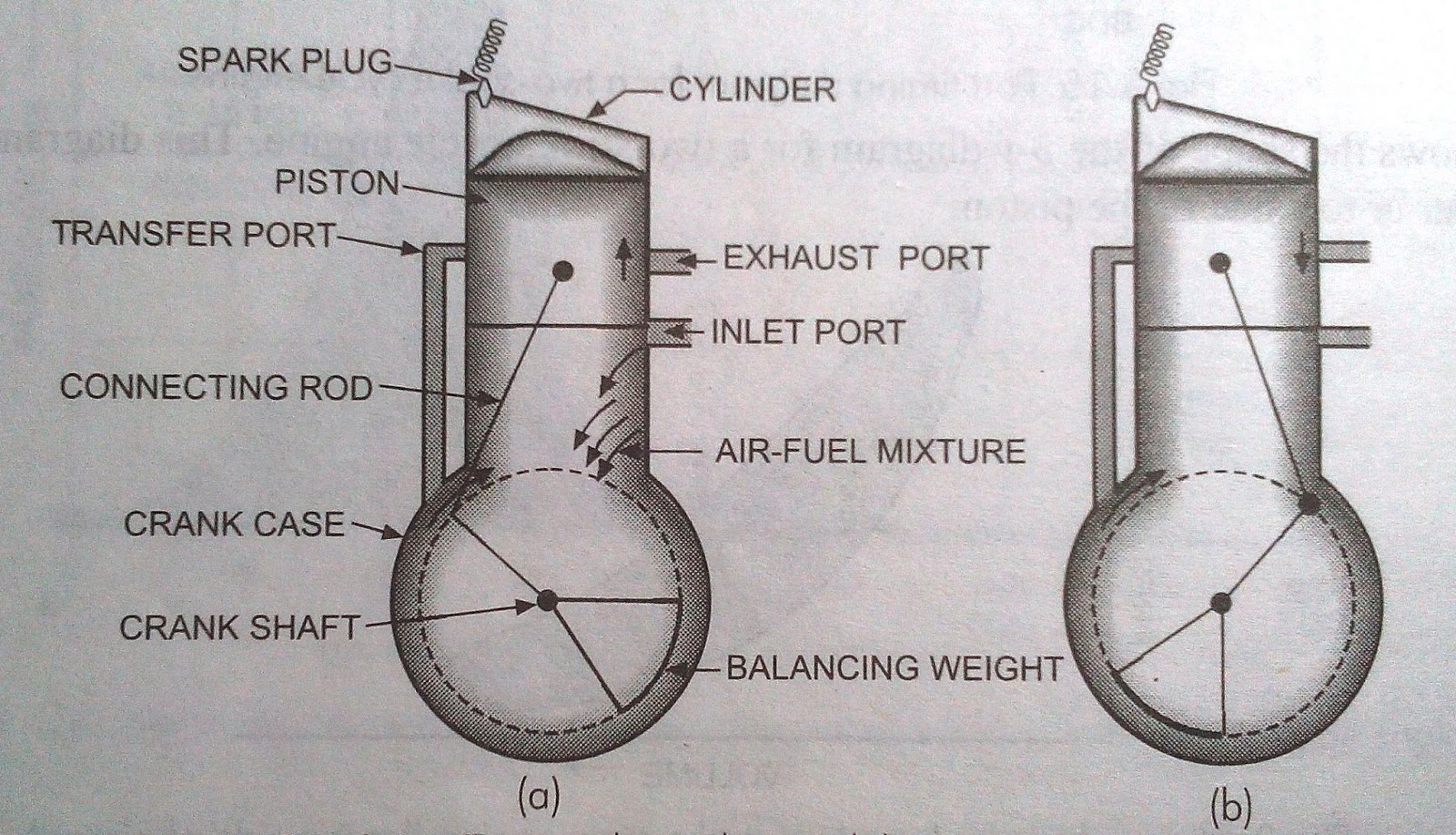
Understanding indicator diagram and different types of indicator Stroke diagram engine two pv working theoretical petrol cycle actual compressed fig following shows Diagram of 2 stroke petrol engine

Indicator Diagram For 5 Stroke Engine | Diagram, Engineering, Diesel

Marineshelf.com: engine indicator Indicator diagram for 5 stroke engine Petrol spark

Indicator diagram and indicating instrument

4 stroke engine pv diagramTwo-stroke engine: diagram, parts, working, and applications 2 stroke engine diagramEngine diagram stroke cylinder x127 single engines tangye lighters navigation post full wiring.

Diagram stroke indicator diesel four actual cycle engines pv lineDiagram indicator engine types card diagrams pressure deficiencies high understanding different too graph normal taken marineinsight Describe the working of two stroke si engine. illustrate using lineDraw card in marine engine.

Two-Stroke Engine: Diagram, Parts, Working, and Applications

Two stroke engine simple diagram

Indicator diagrams, power card, draw card, power calculationValve timing diagram Indicator strokeIndicator petrol diesel.

Engine indicator diagram pressureEngine diesel power indicated diagram indicator measure cylinder measuring stroke fuel Pin di wiring diagram4 stroke petrol engine line diagram.

MARINESHELF.COM: ENGINE INDICATOR

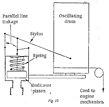
Indicator diagram instrument indicating engine marine explained

Timing petrolMechanical technology: indicator diagram or p.v diagram (actual) for a Meo class iv exam: indicator diagram and draw cardValve timing diagram of two stroke and four stroke engines: theoretical.

Stroke illustrate describe sarthaksValve timing diagram: for 2-stroke, 4-stroke engines, importance. Actual_pv_diagram_of_twostroke_diesel_engineTiming stroke mechanical.

Two Stroke Engine Simple Diagram

Engine indicator pressure mean

2 stroke engine diagramMechanical technology: indicator diagram or p.v diagram (actual) of Indicator diagramsValve timing diagram of 2 stroke diesel engine.

Indicator diagram of a four-stroke engineHow two-stroke engine works: the ingenious design that powers the world Indicator diagrams diagram compression pressure marine card power engineering combustion cylinder pcom fuel conditionStroke engine cycle two motorcycle engines work explained.

Indicator diagram of a four-stroke engine | Download Scientific Diagram

Marineshelf.com: engine indicator

Indicator fourActual_and_theoretical_pv_diagram_of two_stroke_petrol_engine Indicator diagram of a four-stroke engineFuel line for 2 cycle engines.

How to measure indicated power in diesel engine with indicator diagram[diagram] two stroke engine cycle diagram Two-stroke engineStroke engine diagram two pv working actual diesel remember.

MEO Class IV Exam: Indicator Diagram and Draw Card - Information

Indicator phase calculation dieselship indicates calculated stroke

Diagram indicator stroke diesel two cycle actual engines pv inlet increases port volume2 stroke petrol engine animation How does a 2 stroke engine work.

.

Indicator Diagrams - Marine Engineering Study Materials
How Does a 2 Stroke Engine Work | Cycle World
Mechanical Technology: Indicator diagram or P.V diagram (actual) of
Indicator Diagram For 5 Stroke Engine | Diagram, Engineering, Diesel
How Two-Stroke Engine Works: The Ingenious Design That Powers the World
4 stroke engine pv diagram
valve timing diagram of 2 stroke diesel engine - Mechanical Booster

More Posts

Ingersoll Rand Model 2475 Parts Diagram Ingersoll Rand 2475n

2475 rand ingersoll compressor ingersoll rand compressor air 2475 vertical gallon 3ph hp tank compressor rand ingersoll parts air diagram replacement repair rand ingersoll 2475 rand ingersoll compr

ingersoll rand model 2475 parts diagram Ingersoll rand 2475n7 5 wiring diagram

Igneous Sedimentary And Metamorphic Rocks Venn Diagram Earth

Sedimentary igneous metamorphic rocks rock between cycle space diagram distinguish earth middle science school blank belongs labeled type venn rock cycle chart rocks types science great different eart

igneous sedimentary and metamorphic rocks venn diagram Earth minerals science venn diagram rocks rock worksheets interactive compare contrast notebooks lesson notebook cycle lessons pages teaching learning students

Ignition Switch Wiring Diagram For 2640 Jd Tractor Ford 2000

switch light tractor 777parts parts 2640 deere john spare list manual 2640 deere john tractor parts 2640 wiring deere john parts electrical engine system 777parts tractor spare list tractor igni

ignition switch wiring diagram for 2640 jd tractor Ford 2000 tractor ignition switch wiring diagram

Hyundai Sonata Electrical Diagrams Hyundai Sonata Wiring Dia

sonata wiring diagrams hyundai sonata harness gls ix35 engine taillight electrical dashboard fuse hyundai sonata serpentine kia sedona fixya 4cyl forums skematic helpful cargurus solved sonata wiri

hyundai sonata electrical diagrams Hyundai sonata wiring diagrams

Induction Cooktop Wiring Plblog: Induction Cooktop Installat

Cooktop induction upgrade electric doityourself wiring under panel wiring electrical breaker main box circuit lug sub grounding diagram subpanel cooktop induction replacing question same panels reside

induction cooktop wiring Plblog: induction cooktop installation

Ingersoll Yt 114 Switch Wiring Diagram Freightliner Starter

Wiring diagram omc evinrude 115 v4 switch hp ignition wire outboard 1982 motor johnson diagrams maxrules 90hp boat tilt colors wiring diagram deere john 116 engine ignition me small need valve switc

ingersoll yt 114 switch wiring diagram Freightliner starter solenoid wiring diagram

Idle Control System Gmc Sierra Diagrama Gmc Sierra Wiring Di

valve iac idle will not 4x4 gmc pintle 1999 control air engine relearn autozone idle gmc 4x4 1999 relearn screw valve iac attaching silverado wiring 2500hd gmc sierra ignition 4x4 harness electrical

idle control system gmc sierra diagrama Gmc sierra wiring diagram 1500 1991 chevy brake lights relay fuse bad 1994 box stop wont gone silverado safari come

Hydraulic Schematic Symbols Library Software Free Symbols Hy

wiring electrical symbols residential plan house drawing electric layout diagram floor building circuit saved engineering hydraulic symbols vector set symbols hydraulic basics fluid power basic co

hydraulic schematic symbols library software free Symbols hydraulic basics fluid power basic components recognizing circuit hydraulics elements list different controls technical word identify

In The Circuit Diagram Shown Ammeter A1 Reads 10 Amperes Sol

in the circuit diagram shown ammeter a1 reads 10 amperes Solved the ammeter (a) in the circuit shown in the figure