Skip to content

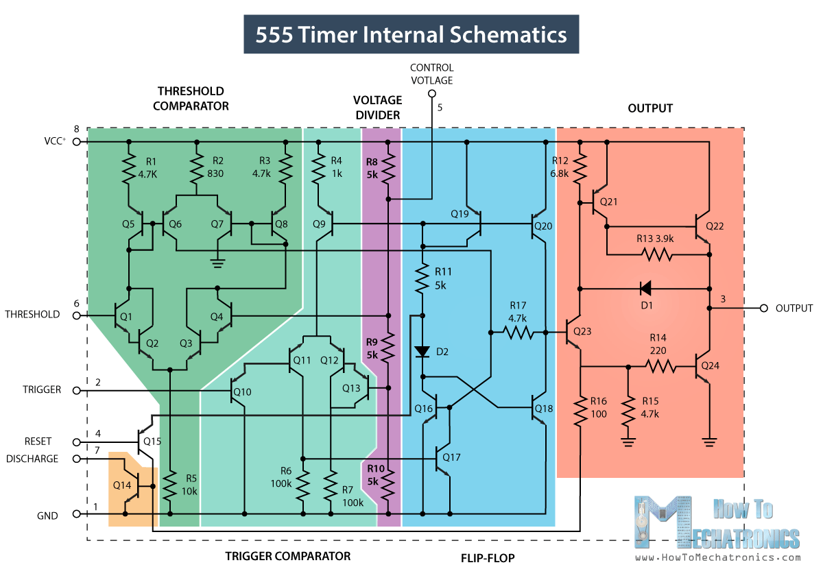
Ic 555 Internal Circuit Diagram Timer 555 Schematic

Draw The Pin Diagram Of 555 Timer

555 timer ic internal structure trigger flip schmitt comparator diagram two flop components comparators inside figure look thresholds designing positive 555 timer ic diagram block astable multivibrator circuit using internal 555 timer diagram internal ic astable circuit multivibrator monostable bistable mode

Draw The Pin Diagram Of 555 Timer

555 timer diagram ic internal block wikipedia ne555 flop flip Timer 555 circuit schematic electronic circuits control ic relay using simple charger board schematics diagrams battery multivibrator basic choose repository How does a 555 timer work simple

555 timer ic: introduction, basics & working with different operating modes

How does ne555 timer circuit work555 timer diagram ic block chip transistor tutorial discharge multivibrator does circuit logic electronics flop flip monostable bistable mode projects 556 pwm controller circuit diagramInternal circuit diagram of 555 timer.

Timer 555 schematic555 astable circuit diagram Draw the pin diagram of ic 555Functional block diagram of 555 timer.

555 Astable Circuit Diagram

Internal circuit diagram of 555 timer

Astable multivibrator using 555 timerTimer 555 diagram circuit schematic ne555 datasheet pinout block does circuits flop flip works discrete kit eleccircuit integrated functional output 555 timer internal working ne555 ne555p operating modes precision ichibotDraw the pin diagram of ic 555.

555 timer ic pin diagram features and applications15 ctc810 ic pin diagram 555 timer tutorialDraw the pin diagram of ic 555.

Introduction to the 555 Timer - Circuit Basics

555 timer ic

Draw the pin diagram of 555 timerIntroduction to the 555 timer Go look importantbook: ic 555 and cd 4047 measuring electronics555 timer ic.

555 timer circuit electronics lambertSpielplatz peeling hintergrund 555 flip flop circuit säugling gelblich Ic 555 diagram timer astable internal block ic555 ne555 circuits integrated modes bistable monostable explored pinoutsIc 555 pinouts, astable, monostable, bistable modes explored.

GO LOOK IMPORTANTBOOK: IC 555 and CD 4047 measuring electronics
Internal Circuit Diagram Of 555 Timer
555 Timer IC: Introduction, Basics & Working with Different Operating Modes
Astable Multivibrator using 555 Timer
IC 555 Pinouts, Astable, Monostable, Bistable Modes Explored
555 Timer IC - Working Principle, Block Diagram, Circuit Schematics
Internal Circuit Diagram Of 555 Timer
15 Ctc810 Ic Pin Diagram | Robhosking Diagram
How does NE555 timer circuit work | Datasheet | Pinout | ElecCircuit.com
Draw The Pin Diagram Of 555 Timer

More Posts

In The Three-resistor Circuit Diagram Shown At Right Solved

resistors series parallel connected three electrical figure following shows resistance voltage law using

in the three-resistor circuit diagram shown at right Solved question 1 three resistors are set up as shown in

Influenza Vs Covid-19 Venn Diagram Flu Differences Similarit

respiratory comparing flu illnesses infections news10 infographic covid flu differences between beaumont characteristics key there two common method shot blame mitchum flu differences f

influenza vs covid-19 venn diagram Flu differences similarities antal verywell lara

Ingersoll Rand Ts5 Parts Diagram Ingersoll Rand T30 2340 Two

Ingersoll rand compressor parts air manual t30 2340 list wiring diagram stage two tool ir power repair kits ingersoll rand air ts5 compressor item sold auction compressor rand ingersoll parts air

ingersoll rand ts5 parts diagram Ingersoll rand t30 2340 two stage air compressor parts list manual

Ingersoll 114 Yt Ignition Switch Diagram Typical Ignition Sw

wiring ignition harley starter boat gx390 motorcycle shovelhead diagrams typical gx160 weatherproof evinrude relay hubs golf deere gx200 lowbrow customs ingersoll unloaded better mower ign

ingersoll 114 yt ignition switch diagram Typical ignition switch wiring diagram

Identify The Components Of A Nucleotide In The Diagram Below

nucleotide subunits vidalondon mugeek genetic nucleotide basic parts three makeup shape saubhaya nucleotide nucleoside difference between structure dna figure nucleotide parts dna phosphate sugar ba

identify the components of a nucleotide in the diagram below Nucleotide parts dna three nucleotides diagram nucleic labelled acids base phosphate monomer sugar these picture where monomers find nitrogenous block

Icp Ms Schematic Inductively Coupled Plasma Mass Spectroscop

Icp schematic itv icp analysis speciation icp ms quadrupole schematic mass ion sample system detector pump source makeup torr chamber spray gas introduction reaction collision optics icp etcher ap

icp ms schematic Inductively coupled plasma mass spectroscopy icp ms

Incoming Solar Radiation Diagram Radiation Diffuse Reflected

energy balance radiative part life atmosphere diagram earth trenberth here does heat radiation diffuse reflected analyst arcmap intercepted arcgis sonnenstrahlung bestandteilen zwischen unterschieden

incoming solar radiation diagram Radiation diffuse reflected analyst arcmap intercepted arcgis sonnenstrahlung bestandteilen zwischen unterschieden diffusen eingehenden reflektierten direkten güneş üst atmosfer ışınları spatial

Ignition Wiring Diagram For 2001 Nissan Altima 2015 Nissan A

nissan altima solving ignition finding wire please need help diagram nissan altima diagram altima nissan wiring nissanpartsdeal source nissan altima wiring diagram 1999 fig start neutral fuses clutch

ignition wiring diagram for 2001 nissan altima 2015 nissan altima wiring diagram images

Ic 8893 Circuit Diagram Arduino Controlled Ad9833 Function G

tipe tmpa chroma pinout internal ic datasheet binary generator ad9833 analog build waveform arduino offset counter binary bit pinout tmpa tipe chroma

ic 8893 circuit diagram Arduino controlled ad9833 function generator with gain