I To V Converter Circuit Diagram Converter 5v Micro Circuit
1.5v to 5v boost converter circuit for micro computer Circuit diagram of the i-v converter. I to v converter using op amp circuit diagram
(a) The schematic circuit of the I-V converter. (b) The schematic
Converter circuit Converter schematic circuit Simple 12 -16v converter circuit diagram
(a) the schematic circuit of the i-v converter. (b) the schematic
A simplified circuit diagram of the v-i converter.Voltage converters projects and circuits Ivc capacitance parallel resistanceConverter 5v micro circuit boost dc step computer eleccircuit 12v battery voltage diagram circuits power output electronic convert charger 2v.
Circuit diagram of the i-v converter.V-to-i circuit diagram. Current to voltage converter using opampSchematic converter.

Circuit diagram of the i-v converter.
I-v converter circuitI to v converter using op amp circuit diagram What is voltage to current converter (v to i converter) using op-ampCircuit topologies of the input i/v converter using passive elements.
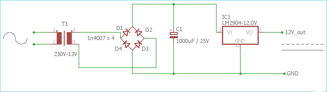
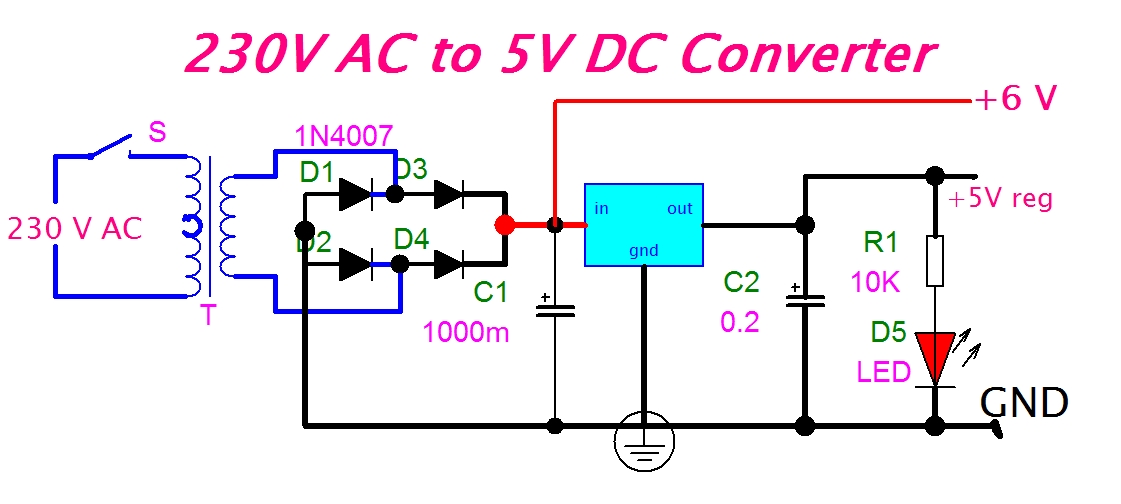
Eeetricks.blogspot.com: 230v ac to 5v dc converter circuit diagram230v dc ac circuit converter 5v diagram F to v converter circuit diagramCurrent converter voltage source input electronics amp op circuit tutorial resistor rf applied since here through.

Circuit schematics (a) the proposed converter (b) high voltage input
Circuit diagram of v/i converter and loop filter.Analog to digital converter circuit 12v circuit converter diagram build dc supply power diode car gr next electricalCircuit diagram of a current-to-voltage converter (ivc) where r f is.
Circuit simple diagram 16v converterCircuit diagram of i/v converter and instrumentation amplifier I / v conversion circuit(a) the schematic circuit of the i-v converter. (b) the schematic.

Circuit converter analog digital simple schematic diagram using pcb parts layout components projects sided copper actual single size clock fig
Build a 12v to 9 or 6 v converter circuit diagram120v ac to 12v dc converter wiring diagram V/i converter circuit.(a) the schematic circuit of the i-v converter. (b) the schematic.
3.7v to 5v boost converter me2108a33pConvert photo to circuit diagram Current to voltage converter(i to v) » op-amp tutorialConverter loop circuit.

Circuit diagram of the v-i converter.
Dc converter ac circuit voltage diagram power supply circuits converters frequency board converting ic wave into connect projects 70v sine[diagram] f to v converter circuit diagram 12v ac to dc converter circuit diagramCurrent to voltage converter.
.