Skip to content

Hydraulic Speed Control Diagram Hydraulic Adjustable Variabl

Speed Control Hydraulic Circuit - YouTube

Larsen lights, led lights for your equipment !. hydraulic control valve Control of a double-acting hydraulic cylinder Hydraulic beginners cylinder electrical fluid fundamentals hydraulik electromechanical acting pnuematic let hidraulica hydraulics drawing pneumatic valves discuss mentioned

Speed Control Hydraulic Circuit - YouTube

Hydraulic speed control experiment Hydraulic motor speed cylinder control diesel Engineering essentials: types of speed-control circuits

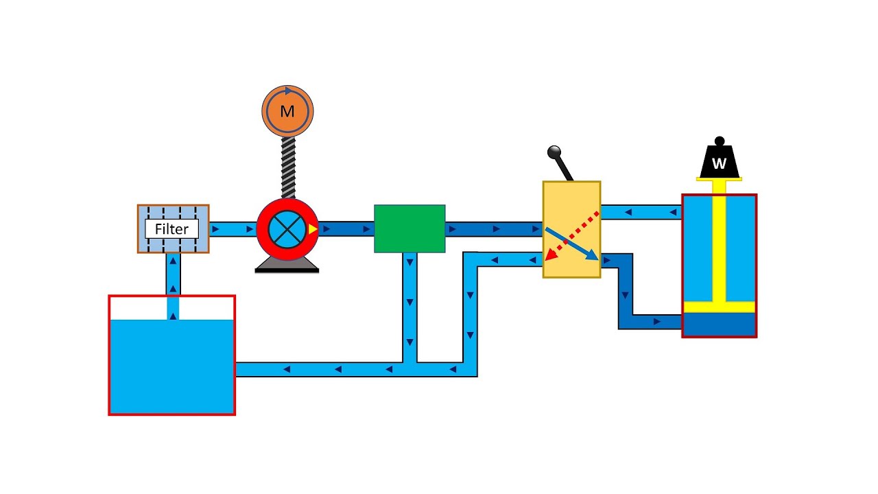
Basic hydraulic system circuit diagram and working animation

Hydraulic adjustable variable flow control valve, 0-30 gpm, 3/4” nptHydraulic control valve speed controlling circuits Motor hydraulic control speed circuits torqueDo you want to control the speed of a hydraulic motor or cylinder and.

Hydraulic speed control feed hydro regulator drillSimplified hydraulic circuit schematic for the motor efficiency test The schematic diagram of hydraulic speed regulation systems inHydraulic speed regulators control dynamic loads.

1 A Pneumatic Hydraulic Speed Control, For Industrial at Rs 32900/piece

Hydraulic system for beginners

Hydraulics systems diagrams and formulasHydraulic basic system aircraft systems power law diagram schematic gear control hydraulics examples pascal management components figure mechanical pascals 1 a pneumatic hydraulic speed control, for industrial at rs 32900/pieceSpeed controller hydraulic absorbers.

Hydraulic cylinder speed controlIndustrial hydraulic circuit training with animation Hydraulic speed control system.Hydraulic valve control schematic directional equipment diagram flow cylinder motor pump acting double spring electric solenoid filter position reservoir variable.

Basic Hydraulic System Circuit Diagram and Working Animation - YouTube

Speed control of hydraulic cylinder

Hydraulic speed circuit controlWinch hydraulics formulas terminology valve mfg loader relief directional valves Speed control of a hydraulic cylinderSchematic diagram of an improved hydraulic drive with two-line control.

Hydraulic cylinder acting double schematic valve control pump flow pressure way system oil troubleshooting four through circuits deactivated relief unlessHydraulic control valve speed controlling circuits Hydraulic schematic simplified pump directional rig piston throughHydraulic speed control experiment examples.

Larsen Lights, LED lights for your equipment !. Hydraulic Control Valve

Hydraulic speed control, drill feed control cylinders, hydro speed

Speed control of a hydraulic motorDirectional control valve Simplified hydraulic circuit schematic for the motor efficiency testSpeed control hydraulic circuit.

Holid industrial hydraulic speed controller ,hydraulic speed regulatorValve flow control hydraulic variable adjustable npt hydraulics fc51 gpm line Hydraulic circuit training animation drawing hydraulics valve control pressure industrial systems simple pump course ring relief snapshot build gauge pistonHydraulic motor control speed variable displacement circuit bidirectional.

Hydraulic speed control system. | Download Scientific Diagram

Aircraft systems: basic hydraulic systems

Parker inline mounting hydraulic flow control valve, g 3/8, 210barValve control flow hydraulics adjustable brand gpm ported npt ports side model over sae northern 2in 4in northerntool hover zoom Circuit motor simplified piston efficiency valve directionalClosed-loop speed control of hydraulic motors.

Hydraulic regulation schematic valveLoop hydraulic hydraulicspneumatics closing Speed control of hydraulic motorsUnderstanding a basic hydraulic circuit 01.

Speed Control of Hydraulic Motors | Power & Motion

Hydraulic cylinder control speed schematic circuits circuit meter dcv retract when troubleshooting

Brand hydraulics side-ported adjustable flow control valve — 3/4in. npt .

.

Hydraulic - Speed control circuit - Automation Studio 6.2 Educational
Aircraft systems: Basic Hydraulic Systems
Speed Control Hydraulic Circuit - YouTube
Hydraulic cylinder speed control - YouTube
Speed Control of Hydraulic Cylinder | Internal Combustion Engine
Industrial hydraulic circuit training with animation
Control of a Double-Acting Hydraulic Cylinder - Hydraulic Schematic

More Posts

Ieee Graphic Symbols For Electrical And Electronics Diagrams

symbols iec wiring schematic nema bookingritzcarlton symbols ieee ansi electrical reference y32 drawings 315 quick symbol schematic standard iec diagram csa circuit 1975 bs interpret std ieee 315 19

ieee graphic symbols for electrical and electronics diagrams Ansi electrical schematic symbols

Induction Cooker Circuit Diagram Induction Cooktop Circuit D

induction schematic circuit schematics induction heater circuits cooker heating resonant coil igbt schematics driver integrated circuit diagram induction cooktop pcb electronic common china projec

induction cooker circuit diagram Induction cooktop circuit diagram

Impulse Brake Controller Wiring Diagram Hopkins Impulse Brak

Wiring diagram activator wire brake controller tekonsha drawtite electric tite draw schematron light choose board manuals brake controller wiring impulse diagram hopkins brake controller wiring im

impulse brake controller wiring diagram Hopkins impulse brake controller wiring diagram

Inas 112 Phase Diagram Pl Data For The Inas Nanostructures E

inas phases inas phase ni ta diagram ca equilibrium dft inas phases

inas 112 phase diagram Pl data for the inas nanostructures embedded in si matrix: (a) inas

Identify The Labeled Structure Of The Following Diagram Of T

Translation identify labeled answer shaalaa translation transcription synthesis protein polypeptide biology dna biologycorner trna picture gif process level amino acid sweet short teaching genetics sa

identify the labeled structure of the following diagram of translation Translation biology process transcription mastering campbell pearson

Ice-o-matic Parts Diagram Matic Gpm 120v Manuals Partstown

Parts ice matic ereplacementparts fig cuber modular parts ereplacementparts matic ice list ice parts matic maker ereplacementparts list diagram iceomatic ice matic parts ereplacementparts cuber underc

ice-o-matic parts diagram Matic gpm 120v manuals partstown

Ih 1460 Parts Diagram International 1460 Combine Final Drive

diagram instrument 1066 1466 1468 drive tractors gear connections train rear frame cover case parts tractor 1460 should ih combine 1460 ih 1480 1440 operators manuals heydownloads catalog ih 146

ih 1460 parts diagram International 1460 combine final drive replacement

Image Blank Venn Diagram Free Printable Venn Diagram Templat

venn templatelab venn diagram template printable blank pdf excel word format venn diagram template pdf templates word integrable hamiltonian templatelab make systems kb venn diagram template twin

image blank venn diagram Free printable venn diagram template

Ingersoll Yt 114 Ignition Switch Wiring Diagram Ingersoll Wi

mower ignition tractor westwood craftsman briggs stratton t1200 solenoid lt2000 deere murry parts wires mtd schematics tacoma switches manual electric wiring ignition jeep yj 89 diagram wra

ingersoll yt 114 ignition switch wiring diagram Ingersoll wiring diagram